NoSc
Presentation at the EMRS H1.5
After the presentation, the presentation will be made public here. Please also join us at our poster presentation H.HP.4. at 2021-06-01T16:30.
Objective
In stratigraphic LIBS analysis, the objective is to follow the change of elemental composition along the incident laser beam. However, due to complex light-matter, light-plasma interaction, fluctuations among the laser pulses and incubation effects, the ablation rate typically varies wildly throughout one LIBS experiment. In this work we present a proof of concept to use a coaxially mounted non-scanning single-spot (NoSc-SiSp) optical coherence tomography (OCT) for in-situ absolute depth measurements between the LIBS laser pulses.
OCT
Optical Coherence Tomography (OCT) is an interferometric measurement, wherein those wavelengths of a broadband light source whose integer multiple fit into the distance to the sample can interfere positively and thus contribute to the signal. As a consequence, unlike a typical Michelson-Morley-Interferometer (MMI), the interference pattern is not repeated when the sample is shifted by a wavelength. Instead, the working range is defined by the lowest common denominator of all the wavelengths of the source.
NoSc-OCT
Unlike standard OCT, we do not use a very narrow, needle-like OCT-beam to scan over the surface of a sample. Instead, a wide OCT-beam is used, losing all the lateral information. This enables us to use OCT coaxially with the LIBS ablation path, passing the same optics and obtain information about the surface and the LIBS crater at the same time.
In A Nutshell
NoScSiSp-OCT signal for various geometries and depths
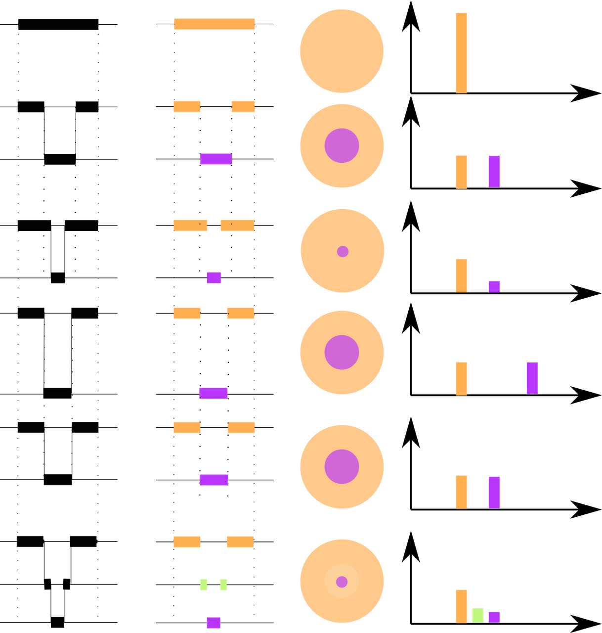
LIBS craters (modelled in left column) differ in depth and width. In the first row, no crater is present, the light is reflected at the surface (second column, orange). The third column gives a bird's eye view on the sample, representing the irritated area. On the right, the OCT signal is represented. In the second row, the light is reflected from the surface (orange) and the bottom of the crater (violet). The ratio of the surface area the area at the bottom of the pit is unity, the OCT signals have the same intensity. In the third row, the area ratio is half, the OCT signal from the bottom is half the amplitude of the surface signal. The signals are twice as far apart for a pit twice as deep. For multiple steps, more signals arise.
Sample
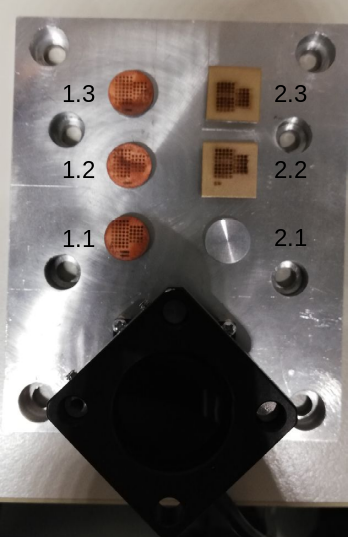
This work has been performed on an Al-Ni-Fe sample (2.2).
Results
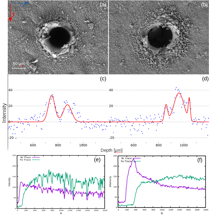
- (a) and (b)
-
SEM images of the LIBS craters.
- (c) and (d)
-
in the NoScSiSp-OCT signals over those craters you can see two peaks in (a), which are the surface and the bottom of the crater in (b) you can see in addition the anular rim of the LIBS ablation.
- (e) and (f)
-
LIBS element traces for N pulses. the Ni-layer is breached at pulse number 200 (left) and 800 (right).
This is the first proof of concept, the resolution and the statistical relevance will be higher in futer studies.
Application in LIBS
Currently, the method of choice to relate the number of laser pulses with depth is to find the average ablation rate for one material by cross-secting number of ablations sites and analyse them with a SEM microscope. To gather statistically relevant data is therefore a tedious and challenging affair. Furthermore, the craters are often damaged during the preparation of metallographic cross-sections. These issues only worsen with mounting complexity of the sample. Our approach is suited for in-situ depth analysis, measuring the difference between surface and bottom of the pit pulse after pulse. Furthermore, the method allows to assess the ablated shape and volume by integrating the intensity of the signal and its depth signal. In combination to the LIBS signal, from which a mass can be derived by attribution of a signal to the species and its relative strength, NoScSiSp-OCT and LIBS can yield information about the sample density in addition to the elemental information throughout the sample.
Outlook
Using NoScSiSp-OCT in a coaxial LIBS setup, we hope to be able to investigate incubation effects on different materials. Furthermore, information about the ablated volume can be retrieved. The LIBS signal intensities are proportional to the emmiting particles in the plasma and thus coupled to the mass of the ablated material. The ratio of both values yields a measure for the density of the ablated material.
Integrated Setup
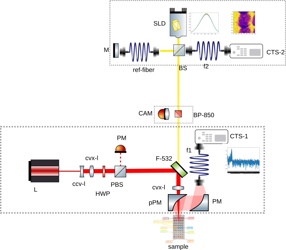
Proposal for emph{in-situ} absolute depth stratigraphy using NoScSiSp-OCT in LIBS. With a standard LIBS setup (middle box), layer by layer of the sample (lower box) is ablated and analysed spectroscopically. The NoScSiSp-OCT (upper box) measures the absolute distance from the surface of the sample to the bottom of the pit.
Acknowledgments
We like to thank Plasmo for granting us access to their OCT device by LDD and Stefan Puchegger for his assistance with SEM imaging. Furthermore we thank LIStrat GmbH for their financial support.
References
- 1
-
A F Fercher, W Drexler, C K Hitzenberger, and T Lasser. Optical coherence tomography - principles and applications. Reports on Progress in Physics, 66(2):239–303, jan 2003.
- 2
-
Dimitris G. Papazoglou, Vassilis Papadakis, and Demetrios Anglos. In situ interferometric depth and topography monitoring in libs elemental profiling of multi-layer structures. J. Anal. At. Spectrom., 19:483–488, 2004.
- 3
-
Karen X. Z. Yu, Logan G. Wright, Paul J. L. Webster, and James. M. Fraser. Deep nonlinear ablation of silicon with a quasi-continuous wave fiber laser at 1070 nm. Opt. Lett., 38(11):1799–1801, Jun 2013.
- 4
-
T.O. Nagy, U. Pacher, A. Giesriegl, M.J.J. Weimerskirch, and W. Kautek. Depth profiling of galvanoaluminium–nickel coatings on steel by uv- and vis-libs. Applied Surface Science, 418:508 – 516, 2017. European Materials Research Society Spring Meeting 2016 – Symposium “Laser – Materials Interactions for Tailoring Future’s Applications”.